


10/29/2012 – ACGHS member Randy Sauder at the recent June 2012 Train Collectors Association National Convention held in Atlanta, Georgia. His “Tool Shop” creation with over 1,000 continuous moving parts won “Best Model Builder” at the recent 2012 ACGHS National Convention in Minneapolis, MN. (Photo credit: Herbert Alfred Mayer)
This 1920’s tool shop was built over a 2 1/2 year span (2009-2012) in about 900 man hours. There are roughly 1,000 continuous moving parts including thousands more parts. Most parts are from early 20th century wood box A. C. Gilbert erector sets. However, some are from like era Meccano, Marklin and other sets. The homemade oak shop frame is similar to the earlier shop that was fortunate to win Best Model at the 2011 national ACGHS Convention in Chicago. Both employ about 500 Popsicle sticks of various length glued on 1/4 plywood to make the first floor. However, that is where the similarity ends. This version is far more complex with some 30 different working tools and machinery. The tools are interrelated using a series of gears and pulley systems. All are powered by one modern Dayton gear motor located under the metal shear on the first level.
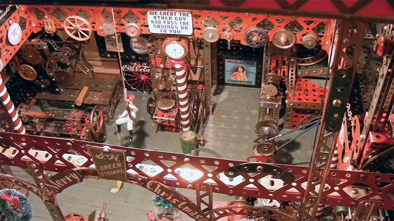
Like on my first shop, regular erector motors in series could have been used. However, more space was required and dependability to run for several hours without overheating was a concern. There are over 100 period advertising signs in the shop. The wood portion of the water wheel at the end of the shop was made using Popsicle sticks. The drive bands are ladies hair bands and rubber o-ring material. The o-rings work best and (thanks to Dave Blood’s tip in a recent ACGHS article on how to make them) all the drive bands will eventually be converted to that version. The shop and all tools are of original design. However, I’ll be the first to admit that hundreds of hours over a 2-3 year period were spent on the Internet researching and looking at pictures of real tools and shops of that era to get ideas. This shop is dedicated to my grandkids and all those who love erector.
Special thanks go to my Dad who in the 1950’s gave me his boyhood erector set and thus set in motion my journey into the wonderful world of A. C. Gilbert. And to my mother’s creativity that somehow spilled over in my direction. Also, special thanks go to all the great erector builders whose many projects can be found on this ACGHS website. Their mass of work helped inspire me to build. And hopefully, this will have the same effect on others. Lastly, thanks to the genius of A. C. Gilbert, Frank Horby (Meccano) and others who gave us the magnificent erector sets.
The shop in the early stages. On the lower left is a small circular milling machine that was eventually discarded and not used in the shop. Nor were the two stacks on the right that I was thinking of incorporating into a large steam engine.
Look closely at this mid construction photo (back upper level left) and you’ll see a four cylinder steam engine that was ultimately scraped. Numerous tools and prototypes were discarded along the way before the final finished version was adopted. You can see the Dayton motor under the Metal Shear at lower left.
Early stages of the somewhat complex drill press gearing. Allowing the drill to turn while at the same time going up and down was accomplished by filing down two round stock axles and then inserting them into a small tube as shown. This created my own gear box. As the axle halves turn (driven by a pulley at the top) against each other they also slide up and down. A separate action on the top rack with the two round BT’s turning (tied together with an offset screw) lift and drop the press using the strip bracket.
During construction various tools were constantly being moved to different locations to determine where they would best fit. None of the three tools shown (Drum Sander, Compressor or Punch) ended up at this location though they look good there at the time.
Looking through the front door at the Metal Shear which ended up at this location (slightly elevated). The Dayton gear motor (power for everything in the shop) was a perfect fit to hide under the shear.
View of the shop during mid-construction. The black and red gearing assembly directly behind the pole on the first floor took about a week to build. It was intended to gear down the revolutions of the water wheel visible just behind the wall. However, a different gearing approach was used and this one trashed. Ultimately, the air compressor ended up at that location.
The shop beginning to take shape. Type I (1914-1924) wide girders were used on the wood frame while Type II (1924-59 era) girders were used internally. Note the different red Marklin girders running length wise near the top of the shop which were used to hide the trolley hoist left right left running mechanism.